Bridge Rectifier-Working Diagram Advantages
The Bridge rectifier is a circuit that converts the alternating voltage into the direct voltage. Rectifiers are made up of diodes and thyristors, to convert AC supply voltage into DC.
There are many applications such as electronic circuits, HVDC transmission where DC supply is necessary. When such supply is needed the AC supply voltage is rectified into DC voltage using a rectifier.
There are three types of rectifier circuit
- Half wave rectifier
- Full-wave rectifier
- bridge rectifier
In this article, we are going to discuss the working principle and construction of the Bridge rectifier, circuit diagram.
A bridge rectifier converts sinusoidal AC voltage into pulsating DC voltage and conducts in both half-cycles of applied AC voltage i.e for a positive and negative half-cycle of AC voltage, unlike a half-wave rectifier which conducts on only one half-cycle at a time.
Construction of Bridge Rectifier
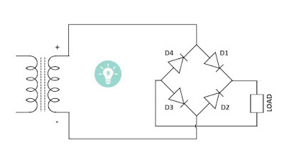
Construction of this rectifier is simple as shown in the above diagram, it is supplied with an AC source and uses four diode D1, D2, D3, and D4 which connects in an antiparallel manner to form a bridge.
The connection diagram of the rectifier’s diode is shown in the above figure.
Working of the Bridge Rectifier
The AC supply which to be rectified is applied to diagonally opposite ends of the bridge through the transformer and between the other two ends of the bridge load is connected.
During the Positive half cycle of AC voltage :
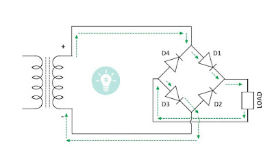
At the positive half cycle of the applied AC voltage. Diode D1 and D3 are forward biased, and Diode D2, D4 reverse biased.
Hence diode D1, and D3 conduct in the first positive half cycle because the diode conducts only in forward bias i.e. when the voltage is applied from the anode to the cathode.
Due to this, For the first positive half cycle D1 and D3 conduct and deliver voltage at the output terminal.
During the Negative half cycle of AC voltage :
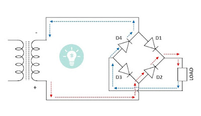
When the opposite polarity of ac voltage means for Negative half cycle Diode D1, D3 becomes reverse biased and D2, D4 are forward biased. So Diode D2, D4 conduct in a negative half cycle producing pulsating dc output at load.
Conducts on both half cycle of ac voltage and we get continuous output in both conducting half cycles of applied ac voltages.
Ripple Factor
The output of the Bridge rectifier consists of DC as well as AC components called a ripple. These ac components are undesirable and create pulsation in the rectifier output, also the effectiveness of a rectifier depends on how much magnitude of ac components present in the output. A smaller magnitude is more effective.
Definition of Ripple Factor: The ratio of r.m.s value of AC components to the DC components in the rectifier output is called a ripple factor.
Advantages of Bridge Rectifier
- Efficiency is high
- Low ripple in output DC voltage
- The center tap transformer is not required
Disadvantages
- The bridge rectifier circuit is more complex than the half-wave.
- Needs four diodes
- Power loss is more as compared to the centre-tapped full-wave rectifier. because two diodes are connected in series create a double voltage drop due to internal resistance. Hence not recommended for small voltage rectification.