VFD-Working Principle and Block Diagram
VFD is a short form of a variable frequency drive also called Frequency converters, which has undergone extremely rapid changes, largely as a result of the development of microprocessor and semiconductor devices and their reduction in prices. However, the basic working principles of frequency converters remain the same. Other names of VFD are variable speed drive, adjustable speed drive, adjustable frequency drive, AC drive. Here we are going to discuss working principle and block diagram of VFD.
Working Principle of VFD
The ability of a Variable Frequency Drive (VFD) to control motor speed lies in its capacity to adjust the frequency and voltage of the power supplied to an AC motor. This allows the motor to run at various speeds based on demand, enhancing efficiency and versatility across different applications.
At the core of the VFD’s operation is the conversion of incoming AC power to DC, followed by a transformation back to AC with a variable frequency. Key components in this process are the rectifier, DC link (or bus), and inverter.
The rectifier converts alternating current (AC) into direct current (DC) using diodes that allow current to flow in a single direction. This conversion sets the stage for manipulating the power flow.
Next, the DC link stores and stabilizes the DC energy, preparing it for conversion back to AC. This section ensures a steady power flow ready for modulation.
The final and most critical part is the inverter. Using insulated gate bipolar transistors (IGBTs), it switches the DC back to AC. By adjusting the frequency at which these IGBTs switch through pulse width modulation (PWM), the output AC frequency variably controls the motor speed. Faster switching results in a higher frequency AC output, increasing motor speed, and vice versa.
It’s ability to tailor frequency is essential to controlling motor speed. By increasing or decreasing the electrical power frequency supplied to an AC motor, they enable the motor to run at various speeds based on demand.
VFD block diagram
The VFD block diagram illustrates the interconnected roles of the main components – the Rectifier, DC Bus/Filter, Inverter, and Control Unit – in producing controlled motor speed.
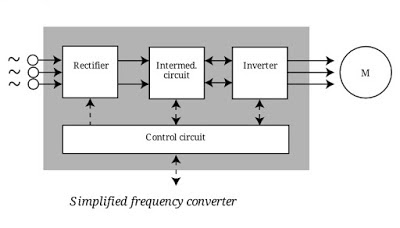
Parts of VFD
- Rectifier
- Intermediate circuit
- Inverter
- Control circuit
Rectifier
The supply voltage applied to the rectifier is a three-phase alternating or single-phase AC voltage with a frequency of 50 Hz or 60 Hz. The rectifier is a circuit that converts the alternating voltage into the direct voltage. Rectifiers are made up of diodes and thyristors, to convert AC supply voltage into the DC.
Intermediate circuit:
The intermediate circuit also called DC-bus” or “DC-link can be seen as a storage facility from which the motor is able to draw its energy via the inverter. It can be built according to three different principles depending on the rectifier and inverter.
The DC bus/filter smooths out ripples and stores the energy. Equipped with capacitors and sometimes inductors, this component filters the DC power to eliminate noise and ensure a clean, stable supply to the VFD’s next stage.
There are three types:
- one, which converts the rectified voltage into a direct current.
- one, which stabilizes or smoothes the pulsating DC voltage and places it at the disposal of the inverter.
- one, which converts the constant DC voltage of the rectifier to a variable AC voltage.
Inverter
The inverter transforms the DC back into AC using insulated gate bipolar transistors (IGBTs). Through Pulse Width Modulation (PWM), it varie pulse durations to control the produced AC frequency, modulating motor speed.1 The inverter fine-tunes electrical energies into desired speeds with precision.
Control Circuit:
The control circuit, or control card, is the fourth main component of the frequency converter and has four essential tasks:
- control of the frequency converter semi-conductors.
- data exchange between the frequency converter and peripherals.
- gathering and reporting fault messages.
- carrying out of protective functions for the frequency converter and motor.
Micro-processors have increased the speed of the control circuit, significantly increasing the number of applications suitable for drives and reducing the number of necessary calculations. With microprocessors, the processor is integrated into the frequency converter and is always able to determine the optimum pulse pattern for each operating state.
VFD Applications
Pump Systems
In water works, from sewage systems to processing plants, they help control the speed at which pumps operate. They can improve efficiency and extend equipment life by providing softer starts and stops. help conserve energy and reduce wear on equipment in pump systems.
Used in Fan Applications
In industrial and commercial settings, control airflows in cooling towers and ventilation systems. By adjusting fan speeds based on demand, they help maintain comfort, health, and safety while reducing energy consumption. They can be effective at conserving energy in fan applications.
Used in Conveyor application
On conveyors in mines, assembly lines, and loading docks, provide precision control. They can modulate speed for smoother starts and stops, protecting materials and machinery. They can help reduce energy consumption in conveyor applications.
In HVAC Systems
In HVAC systems, they control air flow for heating, ventilation, and air conditioning. Energy can be conserved, and motors can adapt to weather conditions and demand.
Reference: Facts Worth Knowing about AC Drives Danfoss