Slip Ring Induction Motor-Working Principle, construction and Its Application
A Slip Ring Induction Motor is a type of asynchronous induction motor. Slip ring induction motors rotor is wound identically to the stator and is connected through rotating electrical contacts known as slip rings. These slip rings let the induction motor have an external resistor connected in series with the rotor winding. The fundamental purpose of slip ring induction motors is to deliver high starting torque, while also limiting starting currents to manageable and optimal levels.
This article delves into one such critical component: the Slip Ring Induction Motor. From its working principles and construction aspects to its comparison with other motors such as squirrel cage motors and prospective applications across various industries, the information aims to illuminate the reader on why these motors are integral to many systems and applications around us.
What Is Slip Ring Induction Motor
Slip ring induction motors are a type of AC motor where external resistor connected to the rotor by means of slip rings. The key components of this type of motor include a stator, a rotor, and slip rings connected to the rotor. The stator and rotor windings are wound for a specific number of poles decided by the desired speed of operation.
Woking Principle of Slip Ring Induction Motor
The working principle of the slip ring induction motor is the same as the squirrel cage induction motor. When an AC supply is given to the stator winding, a rotating magnetic field is produced. This rotating magnetic field induces a current in the rotor winding, due to Faraday’s law of electromagnetic induction.
The rotor current will then produce its own magnetic field. According to Lenz’s law, the rotor magnetic field will be in a direction to oppose the cause of its production. Thus, the rotor magnetic field attempts to align with the stator field but due to inertia, the rotor can never catch up with the stator field causing a ‘slip’. This ‘slip’ is essentially what allows the rotor to rotate and provide mechanical power.
The term slip refers to the difference between the speed of the magnetic field and the rotor speed. If the rotor speed equals the speed of the rotating magnetic field, there is no relative speed between the two, and a zero slip value. However, in real-world operations, this is rarely the case.
Squirrel cage induction motor rotor resistance is very low hence current in the rotor is very high due to this starting torque of the squirrel cage induction motor is poor. But in wound rotor motor, adding external resistance in the rotor circuit makes the rotor resistance high.
in the case of slip ring induction motor, at starting, the rotor current is low because of external resistance. the starting torque is maximum. Also, the slip necessary to generate maximum torque is directly proportional to the rotor resistance.
In slip ring induction motor, the rotor resistance is increased by connecting external resistance, so the slip is increased. Since the rotor resistance is high, the slip is more, thus it is capable of achieving “pull-out” torque even at very low speed. As the motor attains its rated speed, external resistance is cut off from the circuit and the motor runs as a standard squirrel cage induction motor.
Construction Slip Ring Induction Motor
The fundamental construction of slip ring induction motors includes three main elements: the stator, the rotor, and the slip rings.
Stator
Slip ring induction motors consist of two primary components – the stator and the rotor. The stator is the non-moving part of the motor that houses the three-phase windings. The stator resembles a ring carrying a three-phase winding. This three-phase winding is uniformly distributed in identical slots. When the three-phase alternating voltage is applied, it generates a rotating magnetic field in the air gap between the stator and rotor.
The stator core is normally made of silicon steel, which combines lightweight characteristics with high magnetic permeability. This selection reduces hysteresis losses that the motor might suffer during operation.
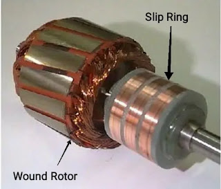
Rotor
The rotor, on the other hand, is the movable part of the motor that rotates to perform mechanical work. It’s constructed with three winding phases, interconnected in a star or delta fashion. Its windings are connected to the slip rings which then are further linked to the brushes. The brushes, made from carbon or graphite, maintain electrical contact with the slip rings, while allowing free rotation.
Demanded in scenarios requiring high starting torque, slip ring induction motors are instrumental in powering cranes, elevators, compressors, and conveyor belts among similar types of machinery. Their wide usage in the industrial arena is due to their ability to handle heavy load applications, delivering smooth, nonjerking, and high starting torque.
Slip Rings and Bearings
Slip rings occupy a critical role in the motor structure. They are mounted on the rotor shaft and rotate with it. Brushes, often made of carbon, maintain electrical contact with the slip rings and permit the external resistances to be added to the rotor circuit.
Bearings are another crucial component of slip ring induction motors’ construction. They support the rotor and allow it to rotate within the stator freely. Bearings must be meticulously produced and installed because motor efficiency and longevity significantly depend on their quality and condition.
Operational Characteristics and Applications
Slip ring induction motors, known for their distinctive construction and operational principles, are capable of providing powerful starting torque. This characteristic makes these motors potentially the perfect fit for tasks that require substantial initial loads, for instance, conveyors, excavators, cranes, and lifts. Additionally, their ability to adapt to various speed requirements further broadens their adaptability in numerous industrial applications.
Difference between Slip Ring Induction Motor and Squirrel Cage Motor
The primary difference between slip ring induction motors and squirrel cage motors lies in their respective rotor designs. With the former, the rotor winding is attached to an external resistance via slip rings and brushes. This configuration enables the resistance to be fine-tuned during the motor’s startup phase, thus moderating the inrush current and enhancing the motor’s starting torque substantially. On the other hand, the squirrel cage motor has a straightforward design with a dense, shorted winding embedded in the rotor. These motors virtually require no external control or adjustments, embodying a “plug and play” function.
While slip ring induction motors offer the advantage of high starting torque, they are also more complex, more expensive to produce, and require regular maintenance. The slip rings and brushes that connect the rotor winding to the external resistance tend to wear out over time resulting in a need for replacement.
Squirrel cage motors, on the other hand, have the advantages of simplicity, greater efficiency, and better reliability since they have fewer moving parts and no slip rings or brushes. The disadvantage is that they have a lower starting torque and no speed control capabilities.
Applications
Slip ring induction motors are generally used in applications where high starting torque is required or where a load has a high inertia. Their adjustable speed makes them suitable for driving crushers, mills, and conveyors in industries such as mining and heavy metal.
Squirrel cage motors find wide applications in domestic appliances, pumps, fans, and office machinery due to their simplicity, high efficiency, and reliability. They are more practical for use in low-power, high-speed operations where speed control and high startup torque is not crucial.
Applications of Slip Ring Induction Motor
Given their ability to deliver high starting torque with a limited starting current, slip ring induction motors find widespread use in various industries and machinery. One of the most common applications is in elevator systems. These motors are capable of providing the large amounts of torque needed to lift heavy weights, while curtailing high-level currents that could potentially damage the electrical supply.
In the printing industry, slip ring induction motors are used in printing presses to provide a smooth start with low inrush current. This is crucial as printing presses involve heavy rolls of paper and a sudden start might disrupt the process and affect print quality.
These motors are also used in situations where the load requirement changes frequently such as in cranes, hoists, and conveyors where the load to lift varies significantly from time to time. In such cases, the slip ring induction motor’s capability to provide high starting torque and adjustable speed is invaluable.
Advantages of slip ring induction
- High starting torque.
- low starting current due to external resistance
Disadvantages of slip ring induction motor
- Higher maintenance costs due to brushes and slip rings compared to squirrel cage motor
- Complex construction
- copper losses are high
- Low efficiency
- Low power factor
Conclusion
Our world is invariably powered by motors, their forms and functions varying widely across industries and applications. The Slip Ring Induction Motor, with its unique construction, functionality, and suitability for certain applications, remains an imperative component in various systems. As with all engineering solutions, understanding this motor type’s advantages and limitations aids in its optimal selection. By appreciating the comparison with other types like Squirrel Cage Motors, and recognizing the intricacies of its construction and operation, the user can aptly assess its role in any operational setting. This information is a torchbearer to foster well-informed decisions and effective motor applications in a mechanically driven world.