Speed Control of Induction Motor-Methods
A three-phase AC induction motor is a constant-speed motor as a DC shunt motor. But the speed of the DC shunt motor can be changed smoothly simply using rheostats. This maintains the speed regulation and efficiency of the DC shunt motor.
But in the case of 3-phase induction motors very difficult to control speed smoothly. if the speed is controlled by using some methods, the performance of the induction motor in terms of its power factor, efficiency, etc. gets badly affected.
as we know induction motors are widely being used, in domestic as well as in industrial applications hence speed control of induction motors is necessary and achieved by using various methods like changing frequency, V/f control or frequency control, changing the number of poles, by the emf injection method. Different speed control methods of induction motors are explained below.
Speed control by changing frequency
This method of motor speed control is impractical for most applications because the frequency of the supply must remain fixed. In some cases where the rotor load is only connected to the generator set, the speed of the prime mover of a generator may be varied to achieve a change in supply frequency and hence change the motor speed.
Speed control by changing the number of poles
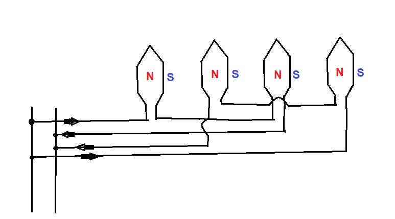
Speed control of induction motor by changing the pole circuit diagram shown above From the synchronous speed equation, we can conclude that a change in the number of poles by making a change in the stator winding connection with the help of a suitable switching method can achieve speed control.
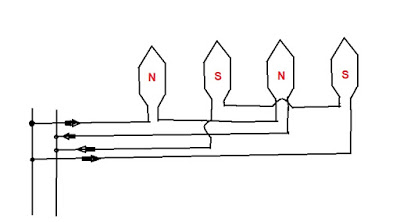
Two separate windings are on the stator producing the same number of poles, one winding creates two N- N-poles, and another winding two S- S-poles. As shown in the figure, This arrangement gives four poles, and the speed at 50Hz is 1500 rpm.
(120 x 50)/ 4
=1500
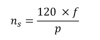
If the connection of one of the winding makes reversed there will be 4 N poles and 4 S-poles depending upon which winding connection is reversed. But in between these 4 poles, other 4 poles of opposite polarity will be created.
Speed control of induction motor by changing the pole circuit diagram shown above From the synchronous speed equation, we can conclude that a change in the number of poles by making a change in the stator winding connection with the help of a suitable switching method can achieve speed control.
Two separate windings are on the stator producing the same number of poles, one winding creates two N- N-poles, and another winding two S- S-poles. As shown in the figure, This arrangement gives four poles, and the speed at 50Hz is 1500 rpm.
Thus stator now has eight poles and its synchronous speed is 750RPM.
Speed Control by changing the slip
Change in slip is made by introducing an external resistance in the rotor circuit of the wound-type rotor, but this produces an effect on the efficiency of the Induction motor and makes speed regulation poor.
These disadvantages are overcome by
speed control of induction motor by EMF injection method
supplying counter-EMF to the rotor at slip frequency
To supply counter EMF by this method requires an auxiliary commutating machine which injects EMF into the rotor at rotor frequency through slip ring arrangement
this method of speed control had the advantage of wide range adjustment in speed without affecting the efficiency of a motor
Supplying EMF to the rotor at the supply frequency
This method requires a commutator for the Rotor
Control speed by cascade connection
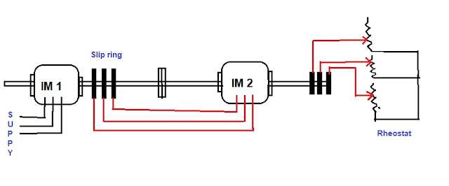
This method of speed control of Induction motors is also known as a tandem connection. When multiple speeds are required motor is operated in a cascade. In a cascade connection, two Motors are rigidly coupled to the same shaft by using gears.
The stator of the first motor is connected to the main supply while the stator of the second cascade-connected Motor is fed from the rotor winding of the first motor.
After that, the rotor circuit of the second motor is connected to the slip ring circuit so resistance may be introduced while starting and for additional speed control when running