Three Phase Full Wave Rectifier Working, Diagram and output waveform
How three-phase bridge rectifier work?
Rectifier is a device that converts AC voltage into DC voltage. rectifier uses a diode and thyristor, to convert AC supply voltage into DC voltage. For economics of generation and transmission of power.
The electric power is usually available in an AC. The AC voltage varies sinusoidal with time and has a frequency of 50Hz or 60Hz depending upon the country.
This AC power is used for lighting purposes, for heating and to run an electric induction motor. However there are many applications like electronic circuits and HVDC transmission where DC supply is necessary.
When such supply is needed the main AC supply voltage is rectified into a unidirectional DC supply using a diode in an uncontrolled rectifier and thyristor in the fully controlled rectifier.
How diodes work?
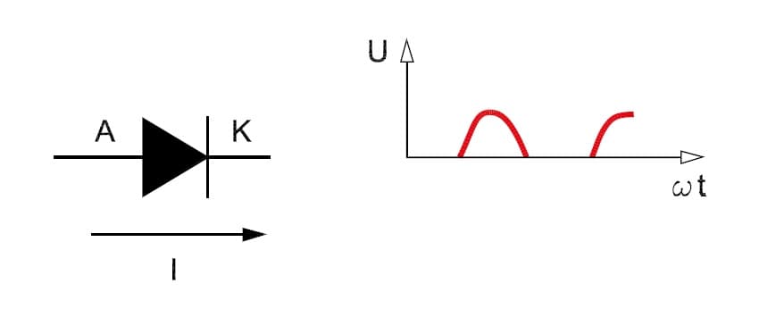
A diode allows current to flow in one direction only: from the anode (A) to the cathode (K). The current is blocked if it attempts to flow from the cathode to the anode. It is not possible to control the current strength, as is the case with some other semiconductors.
An AC voltage across a diode is converted into a pulsating DC voltage. If a three-phase AC voltage is supplied to an uncontrolled three-phase rectifier, the DC voltage will pulsate continuously.
Uncontrolled Three Phase bridge Reactfier working
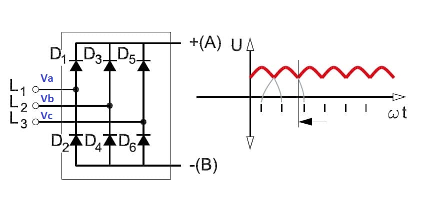
The above diagram shows three-phase full wave uncontrolled bridge rectifier consisting of 6 diodes, also commonly called a 6-pulse rectifier. working of three phase rectifier as follows,
The six diodes can be subdivided into two groups. The first group consists of diodes D1, D3, and D5. The second group consists of diodes D2, D4, and D6. Each diode conducts for 1/3 of the period T (120°).
In both groups, the diodes were conducted in sequence. Periods during which both groups conduct are offset in relation to each other by one-sixth of the period T (60°).
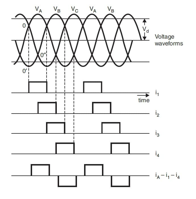
Now let’s discuss the sequence of operation of the three-phase bridge rectifiers circuit, Let Va be the most positive at the starting of the sequence.
Consider point O as shown in the waveform diagram. corresponding to this sequence point Vb is the most negative point, therefore the diode conduction will take place between phases a&b from a to b. the diode will be 1&6 afterword Vb continues to most negative from O’ to O”.
After point O”, Vc is most negative and then conduction starts between phase a & c from a to c through diode 1 &2, Next Diode 3 take over from Diode 1 and current returns through Diode 2.
The complete diode conduction sequence is Diode 1&6, Diode 1&2, Diode 3&2, Diode 3&4, Diode 5&4, Diode 5&6, and again Diode 1&6.
Diode group D1, D3, D5 conducts for positive voltage cycle. When the voltage of phase L1 reaches its positive peak value, terminal (A) takes on the value of phase L1. In the same way, diodes group D4, D6, and D2 conduct for the negative half cycle.
The DC output voltage of the uncontrolled bridge rectifier is constant and represents the difference between the voltages of the two diode groups. The average value of the pulsating DC voltage is approximately 1.31 to 1.41 times the mains voltage with a three-phase supply or approximately 0.9 to 1.2 times the AC voltage in the case of a single-phase supply.
Fully controlled Three Phase Rectifiers working
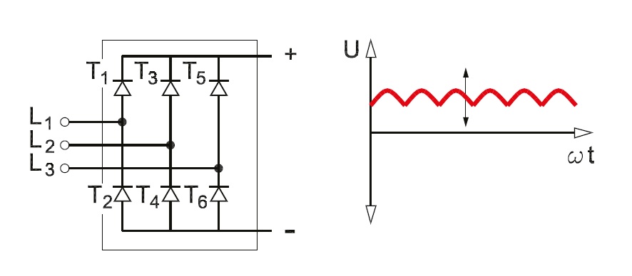
As seen in the above diagram Fully-controlled bridge rectifiers use thyristors instead of a diode as in uncontrolled bridge rectifiers. As a diode, a thyristor allows the current to flow from the anode terminal (A) to the cathode (K) only. However, the difference between the diode and the thyristor is that the thyristor has a third terminal called the gate (G).
When the firing pulse is provided to the third terminal gate, the thyristor will conduct. Once current starts flowing through the thyristor, it will continue conducting until the current drops to zero. The current cannot be interrupted by sending a signal to the gate.
Thyristors are used in rectifiers. The signal sent to the gate is known as the α control signal of the thyristor.α is a time delay provided to thyristor for conduction, which is specified in degrees. The degree value indicates the delay between the voltage zero-crossing and the time when the thyristor is triggered.
Same as Uncontrolled three phase rectifier which use diode, Fully-controlled three-phase rectifiers also divided into two groups of thyristors: One group is named as T1, T3 and T5, and other one is T2, T4 and T6.
If symbol α is between 0° and 90°, the thyristor coupling is used as a rectifier, when it is between 90° and 300° the thyristor is used as an inverter.
In fully controlled three phase bridge rectifiers, α is calculated from the moment when the corresponding diode in an uncontrolled rectifier would normally begin to conduct, that is, 30° after the voltage wave zero crossing. In all other respects, fully controlled rectifiers working is the same as uncontrolled rectifiers.
The amplitude of the rectified voltage can be varied by controlling α. Fully-controlled rectifiers supply a DC voltage with an average value V,
Where,
V = 1.35 x Vmains × cos α.
Reference:Facts Worth Knowing about AC Drives Danfoss