Back to Back test of Transformer (Sumpners Test) Procedure
The efficiency and regulation of the transformer can be calculated using open circuit and short circuit test on the transformer but to measure temperature rise during operation, it is necessary to conduct a full load test on the transformer. for low power small transformers, a full load test can be performed directly by loading. but for a large transformer, it is difficult to load fully and a suitable load to absorb the full load power of the transformer may not be easily available. hence to calculate the temperature rise in the transformer during full load, back to back test of transformer, or sumpner’s test carried out on transformer. it is also called a regeneration test.
To perform the back-to-back test or Sumpner’s tests on a single-phase transformer requires two identical transformers as shown in the below diagram of a back-to-back test of the transformer.
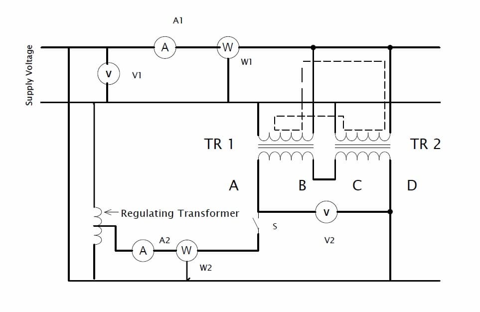
The primary windings of two transformers are connected in parallel and supplied with rated voltage and frequency, as depicted in the diagram. voltmeter, ammeter, and wattmeter are connected to the input side.
The secondaries of the transformers are connected in series with their respective polarities in phase opposition. to check the polarities of secondaries, voltmeter V2 is connected. the voltage range of voltmeter V2 should be double the rated voltage of transformers secondary.
To ensure that the secondaries are connected in series opposition, any two terminals of secondaries are jointed together and voltage is measured between the remaining terminals say A&D, if the voltmeter reading is zero then the two secondaries are in series opposition. Hence terminal A&D is used to perform back to back or sumpner’s test on the transformer.
If the voltmeter shows a voltage equal to or approximately to twice the rated secondary voltage of the transformer, then the winding is connected in the same direction the A&C is jointed, and terminal B&D are used to perform the test.
When the primary circuit is closed the total voltage across the two secondaries in the series will be zero. There will be no current flowing through the secondary winding. Hence transformer behaves like a secondary open circuit due to this reading of wattmeter W1 gives the iron losses of both transformers i.e TR1 and TR2.
Now, a small voltage is injected in the secondary by using a regulating transformer which is excited by using the main supply. The magnitude of the applied voltage is adjusted such that the ammeter A2 shows full load secondary current, and the secondary current produces full load current to flow through the primary windings. The path of this current is shown in a diagram with a dotted line. The readings of W2 will not be affected by this current. Thus wattmeter W2 gives full load copper losses of both transformers.
The ammeter A1 reads the total no-load current of two transformers. Thus in the back to back test, we have loaded the transformer to full load but the power taken from the supply is that necessary to supply the losses of two transformers.
The rise of temperature during full load can be calculated by keeping the transformer loaded for a long time or at least two days.