Buchholz Relay in Transformers | Construction,Operation and Principle
What Is Buchholz Relay?
Buchholz relay is a mechanically operated relay that is used to protect the transformer from internal faults that occur inside the transformer tank like an inter-turn fault. Buchholz relay is an oil and gas-operated device.
The function of this relay to give an alarm in case of an incipient fault in the transformer and to disconnect the transformer from the main power supply in the event of serious internal faults.
Buchholz relay purpose is to disconnect the transformer from the supply in a faulty condition and give an alarm indicating fault type. An installation location is shown in the below diagram.
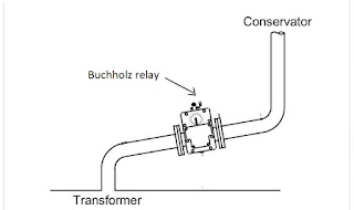
Location: The Buchholz relay is installed in the pipe between the transformer tank and the conservator. The pipe is normally tilted at an angle of 5 degrees. During the normal operation of the transformer, it is filled completely with transformer oil.
Due to an internal fault in the transformer, the temperature of the transformer oil rise and this generates gases into the tank. The generation of gases may be slow or fast depending upon fault type major or minor. The working of the relay depends on the mechanical phenomenon.
Construction
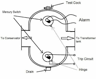
Buchholz relay consists of two hinged floats, one at the upper side and another one at the bottom side in the chamber.
An upper side mercury switch is connected to an alarm circuit which is used to give an alarm during an incipient fault in the transformer tank. And bottom mercury switch is connected to the circuit breaker which isolates the transformer from the supply in case of a series fault in the transformer.
Working Principle
Buchholz relay working principle and operation is based on the gases generated in the transformer tank during the internal fault, whenever a fault is generated in the tank, the Buchholz relay operates and disconnects the transformer from supply or generates an alarm in case of an incipient fault.
When an incipient fault develops in the transformer it produces heat. due to the generation of heat decomposition of solid and liquid insulating material start and it creates inflammable gases. The operation of the Buchholz relay gives an alarm when a specified amount of gases is collected in the relay chamber. By analyzing gases we can get an idea about the type of incipient fault.
- The presence of C2H2 and H2 shows arcing in oil between constructional parts.
- C2H2, CH4, and H2 indicate arcing with the deterioration of phenolic insulation e.g. tap changer fault.
- The generation of gases like Ch4, C2H4, and H2 indicates a hot spot in core joints.
- C2H4, C3H6, H2, and CO2 show a hot spot in the transformer winding.
When gas is generated in the transformer tank because of fault, it rises towards the conservator tank and collects in the upper chamber of the relay.
Hence the oil level in the relay drops and the top float triggers an alarm switch. Gas shall not freely pass from the relay body and escape into the pipework before the alarm contact has operated.
For a serious fault, large volumes of gases are generated in the main tank. which causes a violent flow of transformer oil, this oil in the main tank rushes towards the conservator tank through the Buchholz relay connected in the pipe, which connects the transformer tank and conservator.
Due to the turbulent flow of oil, the lower float tilts to close the contact of the mercury switch. This completes the tripping circuit to open the circuit breaker and transformers get disconnected from the supply.
Check after actuation
Alarm signal
When the alarm signal is given, the color of the gas should be observed through the inspection windows.
The gas may be released or gas samples can be taken for analysis.
Colour of gas due to the operation and fault type:
Whitish gas: It is caused by electric arcing in contact with paper, cotton, and silk.
Yellowish gas: it is caused by wood and Cardboard.
Greyish gas: it is caused by a breakdown of the magnetic circuit.
Black gas: it is caused by free arcing in the oil
Trip signal
If the relay disconnects the transformer, similar checks on the gas should be made to determine the color and the quantity of gas collected. It is always good practice to make a gas analysis. In any case, the transformer should not be immediately re-energized, as this would increase the seriousness of the fault.
Testing Procedures
There are many testing procedures some of them are
- Measurement of the volume of gas necessary to trip the alarm.
- Pressure Withstand Test 2.5 bar for 2 minutes with oil at 100°C.
- Vacuum Withstand Test of 2500 Pa for 24 hrs.
- Rate of oil flow test to operate trip contacts
- Non-stationary vibration tests
Advantages
- This relay detects the internal faults of the transformer and it helps to prevent major faults.
- The intensity and type of fault can be determined without even opening or disturbing the transformer.
- If a serious fault occurs, the transformer can be isolated automatically with the help of the Buchholz relay. these are advantages.
Limitations
The disadvantages of the Buchholz relay are listed below.
- This relay can only be implemented in oil-immersed transformers.
- Its operation is based on the oil level in the transformer tank.
- The response time of the Buchholz relay is too high.
Applications
The applications of the Buccholz relay include the following.
- It can be used at the Entry of air bubbles in the oil
- Insulation failure of the transformer Core bolt
- It can be used where the reduction of oil level will be low due to leakage
- This relay can be used in loose and bad electrical contacts
Related Terms:
How to test electrical relay
What are types of insulation-classes
Open Circuit and Short Circuit Test on Transformer
Transformer Polarity Test