All electrical devices run on electrical power, the consumed energy is measured in terms of watts. the device used to measure consumed power is called a watt meter. to measure three-phase power mainly two methods are used namely two wattmeter method and three wattmeter method.
In this article, we will discuss two wattmeter method of power measurement.
In 2 watt meter method, the current coils of two watt meters are connected in series with R and Y lines. The potential coil of each watt meter is connected to the third line B.
The algebraic sum of the reading of two watt meters gives the total power consumption of the connected load even if the load is balanced or unbalanced.
Total power=W1+W2
Two WattMeter Method
As shown in two wattmeter method connection diagram, two watt meters are connected to three phase star connected load for power measurement.
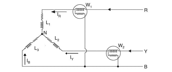
Wattmeter current coils are connected in series with two lines of load R & Y and the pressure coils (potential coil) of two wattmeters jointed to third line B.
The instantaneous power consumed by three phase load is indicated by W1 and W2.
The instantaneous potential difference across W1=eRB=eR-eB
Instantaneous current through W1 =IR
Instantaneous current through W2 =IY
The instantaneous potential difference across W2=eYB=eY-eB
Instantaneous power consumed by load=W1+W2
=IReRB+IYeYB
=IR(eR-eB)+IY(eY-eB)
=IReR-IReB+IYeY-IYeB
=IReR+IYeY-eB(IR+IY)
=IReR+IYeY+IBeB …… as the load is balanced IR+IY+IB=0 and IR+IY=-IB
Hence,
W1+W2=P1+P2+P3
Where,
P1=power consumed by load L1
P2=power consumed by load L2
P3=power consumed by load L3
P= total power consumed=W1+W2
2 Watt Meter Method For Balance Load
Total power absorbed by three phase load can be calculated using two watt meters
When load is considered as inductive then the vector diagram for star connected balance load is

Let three phase rms voltages are ER EY and EB and rms currents are IR, IY and IB
As considered load is inductive in nature, current lags behind the voltage by angle Φ
Current through wattmeter W1=IR
The potential difference across the potential coil of W1 is
W1=ERB=ER-EB
From the vector diagram value of ERB is obtained by compounding ER and EB reversed. and phase difference between ERB and IR is (300-Φ)
Wattmeter W1 reading=W1=ERB*IR*cos (300-Φ)
Current through wattmeter W2=IY and potential difference across pressure coil of W2
=EYB=EY-EB
EB is derived by compounding EY and EB in reversed.
the phase angle between EYB and IY is cos (300+Φ)
but the load is balanced
ERB=EYB=EL and IR=IY=IB
W1=EL*IL*cos (300-Φ)
W2=EL*IL*cos (300+Φ)
P=W1+W2
=EL*IL*(cos (300-Φ)+cos (300+Φ))
using cos (A)+cos (B) formula and solving this we get equation
P=√3 *EL*IL*cos (Φ)