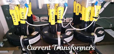
What is Current Transformer-Working, Construction, Type
The current transformer (CT) is a type of instrument transformer designed to measure high-value current in the power system. The primary has few numbers of the turn of heavy wire, and the secondary of the current transformer has many turns of fine wire.
Current Transformers are mainly used to perform two tasks. Primarily to step down high-value power system current to low values typically 5A or 1A that can be suitable for the operation of the protective relays and secondly to measure high current in a power system by stepping down to measuring level for low voltage measuring devices.
Normally current rating of the secondary is 5A or 1A. since the current rating of the secondary is standardized. hence current rating for relay and measuring devices also standardized up to 5A. This allows for an interchange of CTs among different manufacturers of relays and meters.
Working Principle of Current Transformer
The working of a current transformer of electromagnetic type is similar to a power transformer to some extent because both have the same working principle. (electromagnetic induction) but there are some differences like a power transformer is shunt operated device.
while CT is a series-operated device. Current Transformers are connected in series with a power system because the primary current is high and has few turns.
CT is basically a step-up transformer i.e. stepping up a voltage from the primary winding to the secondary winding. Thus the current reduces from primary to secondary winding. Hence stepping down the current value for measuring or protection purposes.
The volt amp rating of the current transformer is small as compared to the power transformer and the secondary current rating is 5A to 1A. but they must be designed to tolerate a high value of short circuit current for few seconds under abnormal system conditions.
Construction of the Current transformer
Depending upon construction there are two types of the current transformer as follows
- Wound type
- Bar type
Wound Type Current Transformer
In wound type, the primary winding is wound for more than one full turn on the CT core. In low voltage wound type current transformer the secondary is wound in bakelite former.
The heavy current primary winding is directly wound on the top of the secondary winding by inserting suitable insulation between them. The current transformers can be ring-type or window-type.
To manufacture the core of CT, the material used is nickel-iron alloy, and the insulating secondary winding core is insulated with the help of end collars and circumferential wraps of the pressboard.
Bar Type Current Transformer
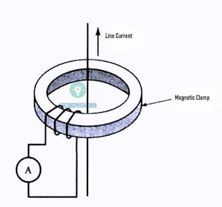
Bar type CT does not contain a primary winding and instead, a straight conductor which is part of the power system acts as the primary winding of the current transformer. In this type of CT primary does not necessarily form part of CT.
The primary conductor which carries current is encircled with the ring-type core made of iron alloy and the secondary winding is wound on it to form a toroid as shown in the diagram. A small gap is left between the start end and the finish end for insulation.
In clamp on CT, the current-carrying conductor itself acts as a single-turn primary winding.
The low range ammeter is connected across the secondary winding of the CT. because the internal resistance of an ammeter is negligible compared with the winding resistance of the CTs secondary. Therefore CT is designed to operate under short circuit conditions.
In the current transformer magnetizing current is too small and the flux density in the core is relatively low Also the core never saturates under normal operating conditions.
Since this type of CT secondary is wound toroidal. Hence it is called toroidal CT. This bar type of Construction has low leakage flux of both primary winding and secondary hence posses low reactance.
Why the secondary of the current transformer should not be left open circuit?
If secondary left open, the current transformer may lose its calibration and give inaccurate readings.
The primary winding is still carrying current and no secondary current is present to counteract its mmf.
The primary winding current acts like a magnetizing current and increases the flux in the core. Increased flux may saturate and magnetize the core when the secondary of CT is closed again, the hysteresis loop may not be symmetrical around the origin but displaced in the direction of residual flux.
Also, the primary current produced large heat over a period of time and may destroy the insulation of winding and saturation of the CT. Result in excessively high voltage across the secondary.
A current transformer is designed like 100:5 which means that it has to multiply factor 20, if the ammeter is connected to 100:5 CT, when 100A current flows in primary secondary Registers 5A. The line current is 5×20 =100A, (2 x Multiplying factor)
Applications of current transformer
- The current transformers are used in the power system to measure heavy current by reducing it to a measurable level.
- This extends the measuring range of ammeters, protecting relays
- Used to operate protecting devices
- Find applications in differential circulating current protection
- Used in distance protection in power system
Read Also..
Open Circuit and Short Circuit Test
Buchholz relay