Star Delta Starter-Working Principle, Control Diagram
A star delta starter is a type of motor starter that is used to control the starting and stopping of three-phase induction motors. It is commonly used in industrial applications where motors of large power ratings are used. In this blog post, we will explore the working principle, control diagram, construction, advantages, theory, and applications of a star delta starter.
wye-delta starter is useful where all six terminals of the motor are accessible.
This starter can be used with all squirrel-cage induction motors that are delta-connected for normal operation.
Star-Delta starter is the simplest starting method for reducing the inrush starting current of the Induction motor.
The reduction of the high motor current causes a reduction of the starting torque of the motor.
therefore specially suitable for drives that are not loaded until after starting. The starting time is longer than with direct starting.
To start a large motor we need a reduced voltage starter, to limit the starting current.
Star delta starter is a reduced voltage starter that applies 1/√3 voltage during the starting time.
Table of Contents
Construction
The construction of a star delta starter consists of three main components: main contactor, star contactor, and delta contactor.
Contactor
In Star Delta Starter three contactors are used the Main contactor, star contactor, and delta contactor.
Main Contactor: The main contactor connects and disconnects the motor from the power supply. A control circuit controls it.
Star Contactor: The star contactor connects the motor windings in a star configuration during the starting process. This configuration reduces the starting current and provides a smooth start for the motor.
Delta Contactor: The delta contactor is used to connect the motor windings in a delta configuration after the starting process. This configuration allows the motor to run at full speed.
A contactor is a heavy-duty relay with a high current rating, used to power up the electrical motor.
The current rating for contactors varies from 10 amps to several hundred amps. The high-current contactor is made from an alloy containing silver.
Arcing during the switching operation of the contactor causes the contact to oxidize. However, silver oxide is still a good conductor.
Overload protection is provided along with the contactors to start the motor. A contactor is not used to interrupt a short circuit current, Unlike the circuit breaker used. Contactor size varies from small to large for high-current appliances.
Overload relay (OLR)
The majority of winding failure is because of overloading, Operation on unbalanced supply voltage, or single phasing due to phase loss which leads to excessive heating to degradation of winding insulation.
the electrical motor requires overload protection, to prevent damage from over-loading the motor, or to protect from a short circuit or internal winding faults. All these conditions are prevented by using a thermal overload relay.
Timer
The function of a timer is to switch the contactor from star to delta after attaining sufficient speed up to 90% of the motor’s full speed.
Fuse unit
The fuse unit is used to protect the motor from overcurrent or short circuit conditions.
The main purpose of the fuse is to protect the motor and is composed of an alloy that has a low melting point.
A strip of a fuse is placed in series with the motor circuit. The working principle is that if the current is in excess then the strip would melt and break the circuit and isolate the motor from the supply.
MCB
A circuit breaker is an automatically operated electrical switch designed to protect an electrical circuit from damage caused by excess current from an overload/short circuit.
Its main function is to break the current flow after a fault is detected. On the Other hand, a fuse, which operates once and then must be replaced, and a circuit breaker can be reset to begin normal operation.
To protect the motor from short circuit conditions and avoid damage to motor winding MCB is used in the star delta starter motor circuit.
push button
Start push button (NO)
This is normally an open(NO) type push button, used to start the motor.
Stop push button (NC)
This is an NC-type push button and is used to stop the motor.
Working principle
The working principle of a star delta starter involves two sets – the star connection and the delta Connected winding. During the starting period, the motor is connected in a star configuration, which means that the voltage across each winding is reduced to one-third of the line voltage. This reduced voltage helps in reducing the starting current and torque. Once the motor reaches a certain speed, the star configuration is changed to a delta configuration, where the motor is connected directly to the line voltage.
Star Connected state


During the starting time, the Main contactor and star contactor remain in a close state and complete the power circuit.
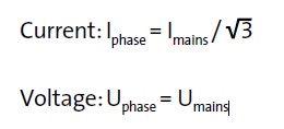
During starting, the motor is connected in a star state. In star connected state Voltage applied to the motor winding is reduced to 1/√3 of the line voltage.
When the motor attains a sufficient speed of full speed i.e. 90% of full R.P.M, the timer connected to the circuit is activated. it disconnects the star contactor first and connects the delta contactor to the circuit, which means It closes the delta contactor.
Open state
Between switching from star to delta, the circuit becomes open and the motor neither remains in star nor delta state. This state is called an open transition state.
Delta state
After activation of the timer, the motor switched from star to delta state.
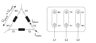
In the delta connected state, phase voltage is equal to line voltage. Hence full line voltage is applied to the motor winding and the motor runs at its rated full speed. delta-connected motor winding is shown in the figure.
Control Wiring Diagram

The control diagram of a star delta starter consists of a timer, a contactor, and an overload relay. The timer is used to control the switching between the star and delta configurations.
Initially, the timer is set in the star position, and the contactor is closed to connect the motor windings in a star configuration.
After a pre-determined time, the timer switches to the delta position, and the contactor opens to connect the motor windings in a delta configuration.
At a starting time, after pressing the start push button, the single-phase supply activates the timer, timer NO contact gets closed and NC contact gets opened. this energized star contactor coil and motor get connected in the star.
After some time motor attains 90% of the rated speed and the timer circuit switches Starter from the star transition state to the delta state, full line voltage gets applied to the motor and the motor continues to rotate at its full speed.
Power Circuit diagram

In the above power circuit, three contactors are used KM3 main Contactor, KM 2 Delta and KM1 is star contactor.
1) During the working of the starter, two contactors remain closed. These two contactors are the KM3 main contactor and the delta contactor KM2.
2) The third contactor KM1 is the star contactor and it takes part only during the starting time of the motor and carries the star current when the motor is in the star state.
3) The current in the star state is 1/3 of the current in the delta state. Hence contactor rating is one-third of motor rated current.
4) During the starting the Main contactor KM3 and Star contactor KM1 are closed initially.
5) After some time, the timer in the circuit gets activated, it opens the star contactor and closes the delta contactor.
6) The switching of the star state to the delta state is done by using a timer, which is connected in the control circuit.
Size of Contactor and overload Relay
Size/rating of Star Contactor
The star contactor only carries star current during the starting of the motor. at startering motor connected in star and star current is 1/√3 times of delta or full load current(FLC).
Hence the size of the star contactor=Motor FLC current X0.33
Rating Of Delta and Main Contactor
Delta and main contactor are utilized during the entire motor operation hence this contactor is rated at 58% of the FLC.
Size of main and delta contactor =FLC X 0.58
Rating of Overload relay
Rating of OLR=FLC of motor and setting must be at 1/√3 XFLC of motor
Advantages
- Star-Delta starters are popular due to their low price.
- There are no limits to the number of times they can be operated.
- The starting current is reduced to approximately 1/3 of the rated motor current.
- Produce high torque per ampere of line current.
Disadvantages
- Only useful to motors where the six motor terminals can be accessed.
- The supply voltage must be the same as the rated motor voltage for the Delta connection.
- Due to the starting current being reduced to approximately 1/3 of the nominal current, the starting torque is also reduced to 1/3.
Difference Between Star Delta and DOL Starter
| Feature | Star Delta Starter | DOL Starter (Direct-On-Line) |
| Starting Method | The motor is initially connected in a star configuration during the starting phase and then switched to a delta configuration for normal operation. | Direct connection to full voltage |
| Starting Current | Reduced during star connected state | High starting current |
| Application Suitability | Large motors | Smaller motors |
| Cost | More expensive due to components | Economical, fewer components |
What is a Star Delta Starter?
Why is a Star Delta Starter used?
What are the advantages of using a Star Delta Starter?
b. Lower mechanical stress on the motor and connected machinery.
c. Cost-effective solution for applications with high starting currents.
Very educative thanks
Thank you for information about Star Delta Starter(wye-delta) working principle
Thanks so very much for the explanations. This is very educating.
Thanks