The Scott connection of the transformer is a standard method of connecting two single-phase transformers to perform the three-phase to two-phase conversion and vice versa. Scott connection of transformer is also known as T – T connection.
In Scott-T connection, two single-phase transformers are connected electrically not magnetically.
One transformer is called the main transformer and the other is known as an auxiliary transformer as shown in the below Scott connection circuit diagram.

The main transformer is center tapped at point D and connected across lines B & C of the three-phase side.
The main transformer has a primary side BC and The secondary of this transformer is a1a2. The auxiliary transformer’s primary is connected between line A and the center tapping D on the main transformer primary.
The teaser transformer (Auxillary transformer) has primary AD and the secondary is b1b2.
In the Scott connection of the transformer generally, the same interchangeable transformers are used in which each transformer has a primary winding having Tp turns and is provided with tapping at 0.289Tp, 0.5Tp, and 0.866Tp.
Phaser diagram of Scotts connection
The supply voltage of the three-phase system VAB ,VBC ,VCA are balanced as shown in the below phaser diagram.
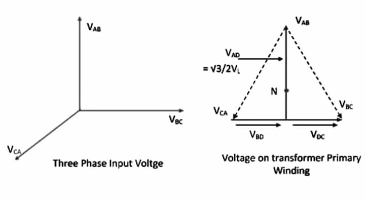
The same voltages are shown as a closed equilateral triangle
|VAB |=|VBC|=|VCA |=|VL|
Let VBC be taken as a reference
VBC = VL ∠0º
VCA=VL∠-120º
VAB=VL∠+120º
Center tapping point D on the main transformer divides winding BC into two equal parts.
Hence,
Number of turns in portion BD= Number of turns in portion DC= TP/2
The voltage VBD and VDC are equal and they are in phase with VBC
VBD=VDC=1/2VBC
= 1/2VL∠0º
The voltage between A and D is
VAD=VAB+VBD
= VL∠120º+1/2VL∠0º

= 0.866 VL∠90º
VAD is the voltage across the primary auxiliary transformer is 0.866 of the main transformer and 90º from it in time.
Voltage VAD is applied across the auxiliary transformer therefore the secondary voltage V2t of the Auxiliary transformer will lead the secondary terminal voltage V2m of the main transformer by 90º.
For the same flux in each transformer, the voltage per turn should be the same. To keep the voltage per turn in same in the primary of the main and auxiliary transformers the number of turns in the primary of the auxiliary transformer that is TAD should be equal to √3/2 Tp

V2t=V2m
The secondary of both transformers have equal ratings since V2t and V2m are equal in magnitude and displace by 90 degrees from each other and they result in a balanced 2-phase system.
Applications of Scott connection
- Used in the electric furnace, where required to operate two single-phase furnaces together and received supply from the balanced three-phase balanced source.
- To link a three-phase system with a two-phase system with a flow of power in both directions.
- Scott connection of the transformer allows conversation from a three-phase system to a two-phase system and vice versa.
