Transformer Polarity test, Additive, Subtractive ,Procedure,diagram
The transformer is the main device of the transmission and distribution network hence its reliability is important in every aspect.
The transformer must be able to deliver the required power to load. single transformer unit is used for distribution purposes but in some cases, more than one transformer is connected in parallel to obtain the reliability of supply and to meet power demand.
Also in a faulty condition, we can take out one of the transformers for maintenance purposes. for this, transformer polarity should be known for the proper connection of the distribution transformer. hence the transformer polarity test is carried out on the distribution transformer.
Mainly two transformer polarities present Additive Polarity and Subtractive Polarity. The importance of the polarity test is that we can avoid a short circuit created by connecting the wrong polarity in the parallel operated transformer.
So before connecting transformers in parallel, it is necessary to know the relative polarities of the transformer. to find out the polarity, a Polarity test is done on the transformer. with the help of the connection diagram method to do a transformer polarity test described in this article.
We perform a polarity test on transformers to ensure that we connect the same polarity windings terminal and not the opposite terminal. If we accidentally connect the opposite polarities of the transformer windings, it will result in a short-circuit and eventually damage the transformer.
Also, other tests carried out on the transformer to find out parameters, efficiency, and loss.
Transformer polarity test
On the primary side of two winding transformers, one winding terminal is positive with respect to the other terminal at any given instant and at the same time, one terminal of the secondary winding is positive with respect to the other secondary winding terminal. and these polarities of the transformer must be known before connecting the transformer in parallel.
A transformer polarity test is important to find out which terminal is positive with respect to the other terminal.
Procedure to Perform Polarity Test on Transformer
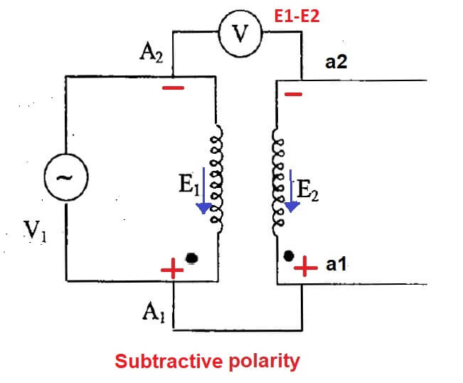
A shown in the transformer polarity test diagram the high voltage side terminals A1 and A2 are marked with a Plus sign and a minus sign. Now terminal A1 of the transformer is connected to the one end of the secondary winding (a1) and the voltmeter is connected between the A2 terminal and a2 of the secondary winding. After that suitable voltage is applied to HV winding.
Consider E1 and E2 are the e.m.f induced into the primary that is HV and LV side of the transformer
If the voltmeter shows a reading equal to E1-E2, the secondary terminal connected to Terminal A1 is positive polarity and mark as a1. and the low voltage terminal a2 connected to terminal A2 is negative polarity indicated by a2 as shown in the polarity test diagram.
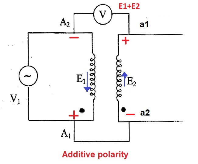
In other conditions, if the voltmeter reading shows the voltage as E1+E2 (additive polarity) then the terminal connected to the A1 is negative and the terminal A2 is positive and labeled as a2 and a1 as shown in Figure
If the A2 it is negative with respect to A1 the secondary terminal a2 is also negative with respect to a1 i.e at an instant voltage from A2 to A1 in HV winding, At the same instant, it is directed from a2 to a1 in LV winding.
Subtractive Polarity
When the connected voltmeter shows a reading E1-E2 difference, the Transformer is said to have subtractive polarity.
Additive Polarity
On the other hand, if the voltmeter reading shows E1+E2 addition called Transformer has additive polarity.
In subtractive polarity, the voltage between A2 and a2 /A1 and a1 is reduced, and lead connected to these terminals are not subjected to the high voltage and in additive polarity voltage increases, and connected leads subject to the high voltage due to this reason subtractive polarity is mostly used.