Tap Changing Transformer- Working, On load and Off load Tap changer
Voltage control is performed by changing the transformer turn ratio. This is achieved by providing Tapping on the transformer winding. In a tap changing transformer, taping is either provided on the primary or on the secondary winding of the transformer.
Most of the electrical loads and equipment are designed to work satisfactorily on constant voltage. So it is necessary to keep consumer end terminal voltage levels within prescribed limits.
Regulating voltage is a requirement in power systems due to the following reason
- To supply the required voltage to the load
- To compensate for voltage drops due to load fluctuations
- To compensate input voltage supply to the load
Voltage per turn is very high in large transformers, even changing a single turn at LV can achieve a large voltage change in secondary.
The principle of regulating secondary output voltage is based on the number of turns in either primary winding or on secondary side winding.
Consider V1, N1, and V2, N2 are the primary and secondary voltage and turns of the transformer.
If N1 i.e primary winding turns decreased, emf per turn on primary side=V1/N1 increases, therefore, secondary output voltage (V1/N2) N2 increases.
On the other hand, if N2 is increased keeping N1 constant, the secondary voltage(V1/N1) N2 also increases. therefore decreasing primary winding turns N1 has the same result as that of increasing the secondary turns N2.
Tapping may be placed on the primary or secondary winding side.
Location of Tapping
A transformer having a large turn ratio is tapped on the HV side, since this provides smoother control of output voltage.
Tap changing on the HV side has to handle low current though more insulation will have to be provided.
It’s hard to tap LV winding since it is placed near to core due to insulation considerations.
On the other hand HV winding is placed outside the LV winding is easily accessible and can be tapped without difficulty.
If the tap changer is designed to operate with the transformer out of the circuit then this type of tap changer is called off load tap changer or NLTC .
And if the tap changer is designed to operate with the transformer in the circuit then it is called an on-load tap changer (OLTC) .
Types of Tap Changing Transformer
- Off Load ( No load) Tap changing Transformer(NLTC)
- On Load Tap Changing Transformer (OLTC)
No Load Tap Changing Transformer
In this type of tap changer, the transformer is disconnected from the supply when the tap has to change. the tap changing is done manually.
Off load tap changer (NLTC) is used for seasonal voltage variation.
The below diagram shows NO load tap changer having six studs labeled from one to six.

The rotatable arm A can be rotated by means of a hand wheel from the outside of the transformer tank.
- At stud 1, 2- Full winding is in circuit
- At stud 2,3 – 97.5% of the winding is in circuit
- At stud 3,4-95% winding is in circuit
- At stud 4,5- 92.5% winding is in circuit
Stop S is provided to prevent the arm A from being rotated in the clockwise direction.
To Change the tap say from 1& 2, the first transformer is disconnected from the supply then arm A is moved from stud 1,2 to stud 2,3 then the transformer is switched on, and now 97.5% of the winding remains in the circuit.
This tap changer is never operated on load, if it were operated on load there would be heavy sparking at studs during arm separation.
It may be damage the tap changer and the transformer winding.
On load Tap changing Transformer
This type of tap changer is used for daily and short period voltage regulation. The voltage can be varied without any supply disturbance.
while the operation of an on-load tap changer
- The main circuit should not be opened otherwise dangerous sparking will occur.
- No part of tapped winding should get short circuited
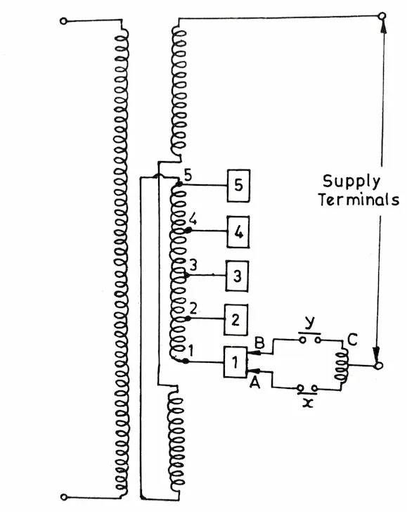
In the above diagram of the on load tap changing transformer, the center tapped rector prevents the winding from getting short circuited.
Transformer tapping is connected to the marked segment 1,2,3,4&5.
Two moveable fingers are connected to the center tapped reactor through switch x&y as shown in the connection diagram.
During full winding of the transformer is in-circuit both fingers are in contact with segment 1 and switch x & y are in closed condition.
Hence half current flows through the switch x via the lower half of the reactor.
The other half current flows through the switch y through the upper half of the reactor, and then to the external circuit.
The current flowing in the upper and lower half of the reactor is in the opposite direction to each other as the whole reactor is wound in the same direction.
Hence MMF produced by both half is equal and opposite. so they cancel each other and the net MMF is zero.
Therefore reactor is almost non-inductive and the impedance is very small also voltage drop in the reactor is negligible.
The Working of On load tap changer (OLTC)
Whenever the change in voltage is required, fingers A&B are brought to segment 2 by the following procedure
Open switch y: due to this entire current now flowing through the lower half of the reactor and it becomes highly inductive followed by a large voltage drop.
Hence reactor must be designed to handle full load current momentarily.
B finger carries no current as switch y is open. therefore it can be moved to segment 2 without sparking.
After closing switch y winding between tap 1& tap 2 gets connected across the reactor.
Now open switch x therefore the whole current will start flowing through the upper half portion of the reactor.
Move finger A from segment 1 to segment 2 and closed switch x. hence the transformer winding between tap 1 & tap 2 becomes out of the circuit.
For further variation in voltage, the same sequence of tap changing of the transformer is followed.
Read Also
Vector group of transformer
Back to Back test of Transformer
Open Circuit Test and Short Circuit Test
scott Connection of the Transformer
transformer oil bdv test procedure